カーテン自動開閉機の自作 プロトタイプ2号機 回路とプログラム
はじめに
初号機から設計概念は変わっていませんが、細かい部品構成は変わってます。
具体的にはモータドライバが変わっているので、回路図を考え直す必要があります。
加えて、初号機で参考にしていた大元のプログラム(esp32-alexa-wemo-emulator)がAlexaと通信できなくなっていたのでプログラムを大幅に変更しました。
お題「#おうち時間」
回路図
モータドライバのMODEピンは浮かせて、IN/INモードを使用することにしました。(IN/INモードとは、入力がHIGHだと出力をHIGHにするモードのようです。)
LOWを入れてもIN/INモードになるので、出来ればLOWを入れといた方がいいと思います。(私は基盤起こしで失敗したので浮かせてますが、回路図では浮かせてません。)
また、モータドライバにはHブリッジ回路が2回路入ってるので、それをパラレルに繋いでより高い電流に耐えれる構成にします。
他は基本的に初号機と同じです。

プログラム
ピン配置について
実はモータを制御するledcwriteで使うesp32のピンを初号機から変更しました。
初号機では、IO12ピンとIO2ピンを使用していたのですが、これらのピンはesp32の起動に関係あるらしいため、使用するをやめました。その代わり、IO14とIO27を使用することにしました。
また、スイッチ用のピンはIO16からIO32に変更しました。回路図の配線を綺麗にするためです。
ちなみに、モータドライバのMODEピンはIO26ピンと繋げる設計にしてプログラムを組んでます。(コメントアウトしています。)
fauxmoESPの応用
以下のライブラリを追加しました。
(fauxmoESPの応用にあたって参考にした記事はこちら)
fauxmoESPのcredentials.hには使用するWifiのSSIDとパスワードを入力します。
メインプログラムは以下の通りです。
#include <Arduino.h>
#ifdef ESP32
    #include <WiFi.h>
#else
    #include <ESP8266WiFi.h>
#endif
#include "fauxmoESP.h"

// Rename the credentials.sample.h file to credentials.h and
// edit it according to your router configuration
#include "credentials.h"

fauxmoESP fauxmo;

// -----------------------------------------------------------------------------

#define SERIAL_BAUDRATE     115200

#define MOT_PIN1            A16//IO14
#define MOT_PIN2            A17//IO27
//#define LOW_PIN             A19//IO26
#define SW_PIN              32//IO32

#define ID_CURTAIN           "curtain"

unsigned long motorStartTime = 0;
unsigned long motorStopTime = 0;

// -----------------------------------------------------------------------------

// -----------------------------------------------------------------------------
// Wifi
// -----------------------------------------------------------------------------

void wifiSetup() {

    // Set WIFI module to STA mode
    WiFi.mode(WIFI_STA);

    // Connect
    Serial.printf("[WIFI] Connecting to %s ", WIFI_SSID);
    WiFi.begin(WIFI_SSID, WIFI_PASS);

    // Wait
    while (WiFi.status() != WL_CONNECTED) {
        Serial.print(".");
        delay(100);
    }
    Serial.println();

    // Connected!
    Serial.printf("[WIFI] STATION Mode, SSID: %s, IP address: %s\n", WiFi.SSID().c_str(), WiFi.localIP().toString().c_str());

}

void setup() {

    // Init serial port and clean garbage
    Serial.begin(SERIAL_BAUDRATE);
    Serial.println();
    Serial.println();

    // Motors
    ledcSetup(0, 2000, 8);//8bit,PWM range 0-255
    ledcAttachPin(MOT_PIN1, 0);
    ledcSetup(1, 2000, 8);
    ledcAttachPin(MOT_PIN2, 1);
    //ledcSetup(2, 2000, 8);
    //ledcAttachPin(LOW_PIN, 2);
    pinMode(SW_PIN, INPUT_PULLUP);//Prevent floating

    // Wifi
    wifiSetup();

    // By default, fauxmoESP creates it's own webserver on the defined port
    // The TCP port must be 80 for gen3 devices (default is 1901)
    // This has to be done before the call to enable()
    fauxmo.createServer(true); // not needed, this is the default value
    fauxmo.setPort(80); // This is required for gen3 devices

    // You have to call enable(true) once you have a WiFi connection
    // You can enable or disable the library at any moment
    // Disabling it will prevent the devices from being discovered and switched
    fauxmo.enable(true);

    // You can use different ways to invoke alexa to modify the devices state:
    // "Alexa, turn yellow lamp on"
    // "Alexa, turn on yellow lamp
    // "Alexa, set yellow lamp to fifty" (50 means 50% of brightness, note, this example does not use this functionality)

    // Add virtual devices
    fauxmo.addDevice(ID_CURTAIN);

    fauxmo.onSetState([](unsigned char device_id, const char * device_name, bool state, unsigned char value) {

        // Callback when a command from Alexa is received.
        // You can use device_id or device_name to choose the element to perform an action onto (relay, LED,...)
        // State is a boolean (ON/OFF) and value a number from 0 to 255 (if you say "set kitchen light to 50%" you will receive a 128 here).
        // Just remember not to delay too much here, this is a callback, exit as soon as possible.
        // If you have to do something more involved here set a flag and process it in your main loop.

        Serial.printf("[MAIN] Device #%d (%s) state: %s value: %d\n", device_id, device_name, state ? "ON" : "OFF", value);


        // Checking for device_id is simpler if you are certain about the order they are loaded and it does not change.
        // Otherwise comparing the device_name is safer.
        if (strcmp(device_name, ID_CURTAIN)==0) {
            motorStartTime = millis();
        }

    });

}

void loop() {

    // fauxmoESP uses an async TCP server but a sync UDP server
    // Therefore, we have to manually poll for UDP packets
    fauxmo.handle();
    //ledcWrite(2, 0);

    if (motorStartTime > 0) {
    if (millis() < motorStartTime + 20000) {
      motRotCw();
      Serial.print(motorStartTime);
      Serial.println("");
    } else if (millis() < motorStartTime + 23000) {
      motRotCww();
      Serial.print(motorStartTime);
      Serial.println("");
    } else if (digitalRead(SW_PIN) == LOW) {
      motRotCww();
      Serial.println("Aluminum foil is touching.");
    } else {
      motStop();
    }
  } else if (digitalRead(SW_PIN) == LOW) {
    motRotCww();
    Serial.println("Aluminum foil is touching.");
  } else {
    motStop();
  }
  delay(100);

    // If your device state is changed by any other means (MQTT, physical button,...)
    // you can instruct the library to report the new state to Alexa on next request:
    // fauxmo.setState(ID_YELLOW, true, 255);
}

void motStart() {
  motorStartTime = millis();
}

void motRotCw() {
  int val = 127;//motor:2.5V→127.5 Vcc:5V→255
  Serial.print("Motor rotates clockwise...");
  Serial.println("");
  ledcWrite(1, 0);
  ledcWrite(0, val);
}

void motRotCww() {
  int val = 127;
  Serial.print("Motor rotates counterclockwise...");
  Serial.println("");
  ledcWrite(1, val);
  ledcWrite(0, 0);
}

void motStop() {
  if(millis() > motorStopTime+3000){
    Serial.print("Motor stops...");
    Serial.println("");
    motorStopTime = millis();
  }
  ledcWrite(0, 0);
  ledcWrite(1, 0);
}
カーテンが開くとき
プログラムを図にしたのがこちら。
カーテンを開ける動作は20秒のモータ正転で行って、最後に糸を緩めるために3秒逆転しています。
カーテンを引っ張って閉めようとするとき
スイッチがGNDにつながっていたらモータが逆転して糸が緩むようになっています。
基盤起こし&はんだ付け
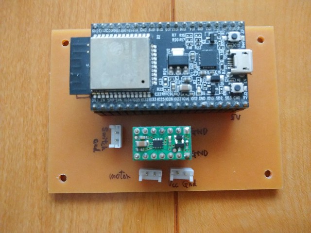
ブレッドボードを使って動作確認を行って問題なかったため、基盤に起こすことにしました。
回路設計で使用したのはKiCADです。
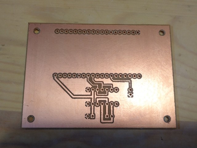
KiCADで作ったガーバーデータを使って自宅のCNCフライス盤で基盤を掘りました。
(本当は中国の会社であるFusionPCBで作って貰おうと思ったのですが、COVID-19の影響か送料が高かったのです。)
ちなみに、裏表を逆にして基盤を起こしてしまう失敗をしたので、くれぐれも気を付けてください。
あと、GNDのはんだ付けが大変でした。


最後に
初号機のプログラムが応用できなくなってしまったため、プログラムを変更しました。
Alexaの更新に、このプログラムがどこまでついていけるのかは謎ですが、今のところ動いています。2020/5/25現在
ちなみにledcSetup()の周波数を調整してギアボックスの音が小さくなるようにしようとしましたが、できませんでした。
タミヤのギアボックスを静音化するのは一苦労しそうなので一旦置いておきます。
次はついにプロトタイプ2号機の総集編です。動作の様子を紹介しようと思います。